Stop to Match the Go - All About 1986 - 1996 C4 Corvette Antilock Brake and Traction Control Systems - Page 2 of 3
 |
 |
© 2009 by Hib Halverson
No use without permission, All Rights Reserved
Traction Control
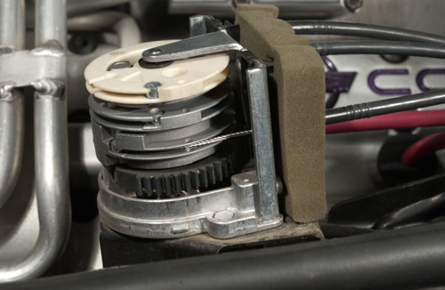
The "Adjuster Assembly" or "Throttle Relaxer" is a motor-operated spindle around which the throttle cables are wound. When the EBTCM commands throttle close-down to reduce rear wheel torque, the Adjuster pulls the cable to decrease the throttle opening.
Image: Author
Bosch brought what the Germans call "acceleration slip regulation" (ASR), to production in the 1987 S-class and 7-series. GM was first to use it in North America on the 1990 Cadillac Allante. It became standard on Corvette for 1992. The Traction Control System (TCS)-some still call it ASR-has the same goal as ABS: controlling tire slip, however, it addresses the other end of the scale, when drive torque exceeds available traction and the rear wheels spin, "break-loose", "burn rubber" or, as engineers say, "exhibit positive slip."
Traction control drove change in some existing ABS components and the addition of new devices to the system. During TCS operation, the EBTCM has capability to retard the engine's spark timing, reduce its throttle opening or apply the rear brakes independently of the driver. The engine control module (ECM) and the EBTCM are linked so TCS can gather engine speed and throttle position data, enable spark retard, cut-off cruise control and, if the car has an automatic transmission, unlock the torque converter clutch (TCC).
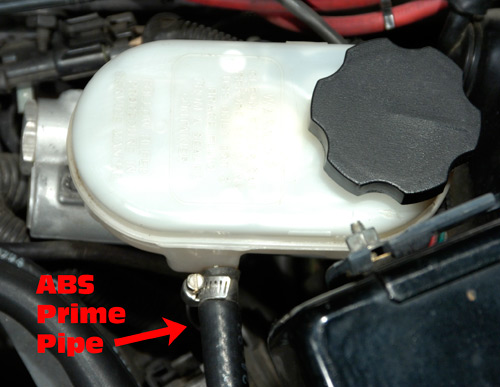
'92-'94 base models and '92-'95 ZR-1s have this master cylinder with a "prime pipe hose" connected to the reservoir. When traction control is active and rear brake intervention is commanded, brake fluid is supplied to the BPM through this hose.
Image: Author
A new piece of equipment, called either a "throttle relaxer" or an "adjuster assembly," was added under the hood to enable the EBTCM to control the engine's throttle body via additional throttle cables. When TCS applies the rear brakes, it needs a supply of brake fluid, so '92-94 base/'95 ZR-1 systems have a "prime pipe" which brings fluid into the BPM from the master brake cylinder. The '95 base-'96 system uses a "prime valve" inside the BPM to supply fluid. TCS detects positive slip at the rear wheels using the same wheel sensors as ABS, along with engine rpm information. If the rear wheels start to spin up, it has a three-step strategy. First, the EBTCM commands the ECM to retard spark but, at no time, will the spark come later than top-dead-center. While spark retard was implemented for MY92, the '93-'95 ZR-1s had that function disabled.
If spark retard doesn't control slip, the EBTCM reduces throttle opening. If the wheel spin still is not controlled and vehicle speed is below 50 mph, the EBTCM will turn on the BPM's pump to apply the rear brakes. It can do that with a differential basis, if necessary, when the system detects a yaw component in combination with wheelspin.
When Trouble Strikes
When ABS diagnostics discover a problem, the system is disabled leaving the base brakes unaffected, information about the fault is encoded in the controller's memory, the (MY86-'89) "Antilock" or (MY90-'96) "Service ABS" warning light comes on and you're in for an ABS diagnostics session.
 |
 |
Click image for larger view
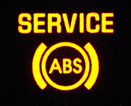
When you see this light on, the ABS controller has set a fault code and you have a diagnostic session ahead of you. If you use "flash code" diagnostics, which we'll discuss later, you'll "decode" codes by watching this light flash. Image: Author |
Click image for larger view
ABS/TCS diagnosis and service requires good service data. At minimum, you need the FSM and, if you find any of the old GM training publications, buy them. Image: Author. |
First, you need service data. No aftermarket repair manual available to consumers covers ABS/TCS adequately. You need a GM Service Manual for the model year of your Corvette and, if it's an '87, '88, '90 or '91, you, also, need the Section 8A Supplement which contains part of the ABS troubleshooting data. They're available from Corvette Central. Also of value are two GM training publications Bosch 2U/2S Antilock Brake System (PN 15005.0B-4) and Corvette ABS/ASR Operation and Diagnosis (PN 13003.02-1). Both are out-of-print but might turn-up on eBay Motors or at swap meets. If you see them; bid on or buy them.
Turn the key to "run" (some techs say, "key-up") but don't start the engine. If the service light comes on, but goes off 2 seconds later, the problem is intermittent. If the light flickers briefly, you may or may not have a problem. The Service Manual has information on either of those scenarios. If the service light stays on, you definitely have trouble and what's next depends on the model year of the car.
While all C4 antilock systems have on-board diagnostic capability, with ABS-2, there's a catch: its only "kinda-sorta on-board" because fault data cannot be read directly. A unique electronic device, the "ABS Tester" (PN J-35890), is required to translate fault data from '86-'89 EBCMs into information useable by those attempting to diagnose the system. Whoever at GM allowed Bosch to get away with this should have been fired-or at least transferred to the Cobalt trunk interior trim group. This gets worse. Today, J-35890s are virtually nonexistent so, unless you run across an ABS Tester on eBay Motors; in a practical sense, other than the "Antilock" warning light coming on when there's a problem, any on-board diagnostic ability ABS-2 has is useless. Nevertheless, there are diagnostic procedures DIYs can use to solve the most common problems.
'86-'89 "Off-board" Diagnostics

Another item required in any ABS-2 diagnosis or repair is the Factory Service Manual. Available from Corvette Central.
Image: Author
If you have a problematic ABS2, read the factory Service Manual first. In Section 8A, cell 44, is a list of troubleshooting hints. Perform items 1-7 in the list. After that's done, key-up the ignition. The amber "antilock" warning light in the DIC should come on for a few seconds while a bulb check and the EBCM Function Check takes place, then go off. If you don't see the light, see Service Manual, Sec. 8, cell-44, "Symptom directory" under "chk antilock lt" and follow the instructions. If the light stays on, something in the ABS electronics caused a self-test failure. With no ABS Tester, from here, diagnosis of ABS-2 can get tedious, but considering the cost of replacement controllers; it may be worth it.
Chris Petris, who owns the "Corvette Clinic," is a technical writer for Corvette Enthusiast magazine and is experienced in early-C4 ABS service, told us, "If the service light is on, once in a while, we've seen a pump motor relay bad or, in a some instances, we've found a couple wheel sensors out, but most often, the 'module relay' was the culprit. 95% of the time, if the light's on; we find that relay bad."
The module relay-also called an "over-voltage protection (OVP) relay"-which controls power to the EBCM, is mounted adjacent to the brake controller in the well behind the driver seat. Sometimes, you can flick it with your finger, recycle the ignition and the system will work. If that happens, replace the relay because it's intermittent, however, if you flick the relay and ABS is still inoperative, test the relay with either a 12v test light or a DMM. The test procedure is in table A in cell-44 of Section 8A in the FSM and replacements, (PN 1636973) can be obtained from GM Parts dealers such as Tom Henry Racing.
We, also, talked to Corvette technician David Fulcher and he offered, "If the (service) light comes on for bulb check, flashes once then stays on, most likely you need a solenoid relay, the silver one on top to the (brake pressure) valve."
Faulty wheel sensors can also be an issue. If they need to be tested, the manual calls for the J-35592 "ABS Pinout Box" and instructs not to probe the ABS harness connectors, however, it's possible to test wheel sensors by disconnecting the EBCM connector then probing its pins. If you take this route, we can't emphasize enough the extreme care you must exercise to avoid shorts because the connector pins are small and very tightly spaced. David Fulcher suggests buying a spare set of test leads for your DMM and soldering sewing needles to the probes. Smart guy, that Fulcher.
 |
 |
Click image for larger view
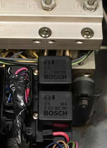
These are ABS relays. Shown is 1995, but '86-'89 is generally similar except that there are three relays (2 located here and a third, the module relay, elsewhere in the well) rather than two. Image: Author |
Click image for larger view
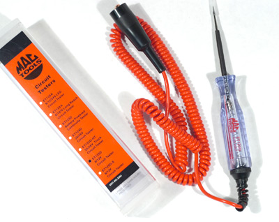
For diagnosis and service of the ABS-2 system and, to a lesser extent, in service of the -2S and -5 systems, you may need a good 12-volt continuity tester or test light. Shown is the Mac Tools model ET-125D, one of the best on the market and what's in our tool box. Image: Author. |
In testing sensors, if you find the resistance of a sensor is out of the range listed in table F on cell 44 of Sec.-8A., then disconnect the sensor connector at the wheel to isolate it from the harness and test again. If the sensor then tests good, look for a short or high resistance in the wiring between the sensor connector and the connector at the controller. If sensor testing finds no trouble and the module relay checked ok or was replaced but the antilock light still stays on at key-up, you need to test the ABS diode, lateral acceleration switch and brake light switch. See Sec-8A, cell-44 tables D and E or Sec-5, which covers the base brake system.
Following that, check all accessible sections of the ABS wiring harness for shorts or opens. In addition, check the ABS chassis ground. In a coupe, it's under the trim on the left B-pillar and, in a convertible, it's under the carpet or trim on the right side of the cargo area. If you test all those items and they're ok, then there's a good chance the EBCM has failed.
If the antilock light goes out after key-up, start the engine. During cranking, the antilock light should be on, and then go off when the key is in "run". Drive a short distance. You should hear the ABS in-motion self-test as you pass 3.6 mph. If the self-test fails, the antilock light will come on. If that happens, check the pump motor relay, mounted on the BPM. A quick test is to remove the pump motor relay, key-up, then jump pin 30 to pin 87 of the pump relay socket. If the pump doesn't run, consult Sec. 8A, cell-44, Table G in the Service Manual for further tests to determine if the problem is with the wiring or the BPM, itself.
If the pump runs, do the second part of the quick test. Connect a test light between pins 85 and 86. Raise the car on a lift or support it with jack stands then have an assistant start the engine and accelerate the rear wheels to 5 mph while you watch the test light. The light should come on between 3 and 4 mph, as the controller attempts to self test the system. If the test light comes on, replace the pump motor relay (PN 12513301). If the light does not come on, consult Sec. 8A, cell-44, Table G in the Service Manual for further tests to determine if the problem is with the wiring or the BPM, itself.
If you replace the pump motor relay and the system still fails during the dynamic self test, check the solenoid relay which is on the BPM, next to the pump relay. The instructions for testing it are in Service Manual, Sec. 8A, Cell 44, Table C. If the solenoid relay is ok or is replaced but the dynamic self-test still fails, using a DMM, check the resistance of the BPM solenoids as discussed in Sec. 8A, Cell 44, Table B. If resistances are anything other than specified, replace the BPM as discussed in Sec. 5E of the Service Manual.
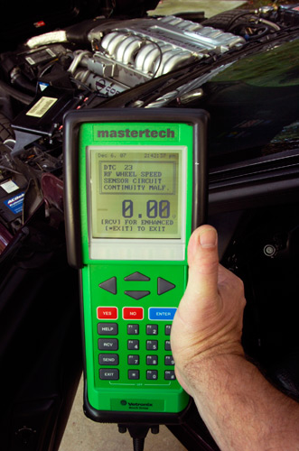
The Bosch Mastertech scan tester reading the memory of a 1995 EBTCM. Code 23 is set. That's a wheel sensor fault we simulated by disconnecting the right front sensor.
Image: Author
Lastly, David Fulcher told us that if the antilock light comes on only after driving awhile, sometimes it's an intermittent ground (discussed above) but most likely it's an intermittent wheel sensor. He added that Fluke DMMs can be particularly valuable in tracking down intermittent sensors. Disconnect the EBCM harness at the controller then road test the car with the meter reading sensor voltages. If the voltage spikes or drops-out, you know the sensor or its harness is faulty.
And what about clearing fault data from ABS-2 after repairs? Once service work is complete, disconnect the battery for ten seconds to erase the data, then at the next key-up, if the system self test is successful, the antilock warning light will go out.
'90-'96 On-Board Diagnostics
Thankfully, starting in MY90, GM required Bosch to build ABS with diagnostics similar to that of the car's engine computer. If there's a problem, fault information is stored as "diagnostic trouble codes" (DTCs). There are two kinds of DTCs, "current", which identify faults existing at the time of the diagnostic session, and "history," which identify faults which do not exist during the session but did exist at some time in the previous 99 ('90-'91) or 49 ('92-'96) ignition cycles. There are two ways to retrieve DTCs: 1) using a scan tester, a hand-held computer dedicated to automotive diagnostic work and which is more common than the ABS Tester or 2) using either "flash code" diagnostics or "CCM diagnostics".
Scan testers communicate with the EBCM or EBTCM and can read DTCs, display ABS parameters in real time, display a limited history of conditions present when a DTC sets, record a "snapshot" of data for use in solving problems and take control of certain system functions for diagnostic purposes. A "scanner" is the best way to diagnose ABS/TCS problems. Some may scoff at professional-grade equipment for DIY work, but trust us-diagnosing ABS/TCS is easiest with a tester and, once you have it, you can, also, given the proper software, diagnose engine and body computer problems. Best scanners for C4 owners are the TECH1 or Mastertech, both manufactured by Bosch Diagnostics or that company's predecessor Vetronix Corporation. The "T1" was the GM dealer tester from 1985 to 1997, but is now out of production and no longer supported. The Mastertech is Bosch's high-end aftermarket tester which shares all T1 functions and has significant additional abilities. Both, when equipped with chassis software, support '90-'96 ABS/TCS. New Mastertechs are available from Bosch. Both are available on the used market. Other testers support C4 ABS, such as units from Mac Tools, but we use a Mastertech because Bosch's relationship with GM makes its equipment the best developed for diagnosing Corvette computer systems. There are more-affordable, "consumer-grade" testers on the market but none support ABS/ASR diagnostics on C4.
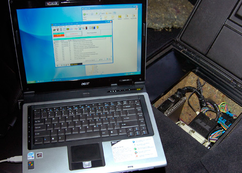
EASE is a heck of a good value if you already have a notebook PC capable of running Windows 98 or better. We use an ACER running XP Home. For this image we simulated some DTCs by disconnecting some wheel sensors. Also, note the NAPA reman controller installed for testing.
Image: Author
"PC Scan Tool", is a software-based scan tester published by EASE Diagnostics which runs on a personal computer and supports '90-'96 ABS. We evaluated PC Scan Tool on an Acer 5672 notebook PC running Windows XP Home and found it outstanding software for C4 ABS/TCS diagnosis. EASE PC Scan Tool is a great value if you already own a laptop and want a full suite of Corvette diagnostic software which supports not only ABS/ASR but also the engine and body computers. One big advantage PC Scan Tool has over a hardware device like the Mastertech is the ability to display a lot more data parameters at one time.
No Tester? Watch the Flashes
If you have a '90 or '91 but no scan tester, enable flash code diagnostics, by jumping pin H of the diagnostic link connector (DLC) to pin A or a chassis ground and then keying-up. The Service ABS light will come on for 4-sec., then start blinking two digit DTCs. Each digit is signified by half-second-apart flashes. One second separates the digits. Codes are flashed three times with a 3-sec. pause between. Each sequence is bracketed by code 12, signifying the sequence's start and finish. Say you have DTC21, a right front wheel sensor fault. The light flashes once, then twice (12), three times in succession. Next, it flashes twice, then once (21), repeating that three times. Finally, it flashes code 12, again, three times in succession. Numerically, it's: 12-12-12-21-21-21-12-12-12. A quirk of flash code diagnostics is five current codes which cannot be read so, if the Service ABS light is on, but you only get code 12; you need a scanner.
Use CCM (Central Control Module) diagnostics if you're working on a '92-'96 and lack a tester. To put the CCM in diagnostic mode, with a '92 or '93 having a 12-pin DLC, jump pin-G to pin-A or a chassis ground or, on '94-'96 16-pin DLCs, jump pin-12 to pin-4, pin-5 or a chassis ground, then key-up. The IP display will show fault codes and the module in which they are stored. ABS/TCS is module nine. DTCs show on the instrument panel display where vehicle speed is normally seen. An extensive discussion of CCM diagnostics is in the Service Manual for the model year in question.
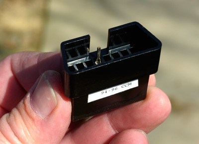
This is one of Zip Products' grounding plugs. This particular unit enables CCM diagnostics on a '94-'96, but the set of plugs includes a similar unit for ABS. Using these tools is easier than fumbling with jumper wires.
Image: Author
To make flash-code and CCM diagnostics work, you've got to jumper across DLC pins. In most C4s, it's tough to see the diagnostic connector well enough to count pins. Zip Products has the solution: grounding plugs which snap onto the DLC. We've used a set of these plugs '94-'96 (PN TL-163) and they are a great idea. You simply push one on the DLC, then key-up-way easier than fussing with jumper wires. A set of them (PN TL-162) is, also, available for '86-'93, 12-pin DLCs.
What to do with DTCs once you have them? Start with the FSM or, for MY87, '88, '90 or '91, its Section 8A Supplement. Troubleshooting information is arranged by code and presented in a flow-chart or "trouble-tree" form where an action is specified followed by a question. The next action is based on the answer. You move through the flow chart, step-by-step until you resolve the problem. When attempting to solve an ABS problem, keep in mind that the majority of automotive electronics faults are caused by wires and connections, so always look for damaged wires, loose fuses, faulty connectors, relays not properly seated, corroded contacts and that sort of thing. A common C4 ABS problem is a loose chassis ground connection. In a coupe, the ABS ground is on the left B-pillar and, in a convertible, it's on the right side of the cargo area. Always check them.
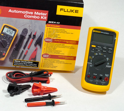
Some solutions require a scan tester, in which case, if you're working without one, you'll have to either acquire the equipment or take the car to a service facility which has it. Some DTCs require a digital multimeter (DMM) which is used to measure voltage, resistance and other electrical parameters and should be a part of any serious DIY's tool box. We prefer the Fluke 88V, which is designed specifically for automotive work, or the Fluke 87, the GM dealer DMM (PN J-39200-A). They're built to service trade standards and they have a record feature which can be useful when troubleshooting elusive, intermittent ABS faults. There are less expensive DMMs than the Flukes-the Actron CP7677 is a good one-but whatever the price range, keep in mind a key DMM property: impedance. Do not use a DMM with less than 10 megohm input impedance for automotive service work.
 |
 |
Click image for larger view
Our favorite DMM, the Fluke 88V. Obviously, we like the Fluke's accuracy and durability but another neat thing is its user-friendliness. For example: need to change probes? Just pull off one set and push on another. Or, mix and match probe ends. Image: Author |
Click image for larger view
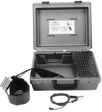
This is the breakout box for MY90-'96 applications. Also required is one of two adapters. Both are available from Kent-Moore. Image: SPX Kent-Moore. |
Other special tools some DTC solutions may require are: for '86-'89, the "Pinout Box" (PN J-35592) or, for '90-'96, the "Breakout Box" (PN J-39700). Each connects between the controller and the wiring harness to allow easy testing of circuits, some of which may need to be energized during testing. The later box, also, requires an adapter and there are two: J 39700-10 for '92-'94 base/'95 ZR-1 and J39700-15 for '95 base/'96. In some situations, you can achieve similar tests by carefully connecting the DMM to harness connector pins, however, in other situations, you cannot perform the required test without the breakout box and, in any event, the box is always easier to work with. When your diagnosis leads you to these tools, take the car to a service facility which has one or, if you're a well-heeled DIY wanting either of these tools, order them from SPX Kent-Moore, the supplier of GM service tools.
David Fulcher told us, "In the rear, the exposed sensors tend to accumulate metal filings from the rear brakes. After a while that can start to knock out the signal. The early ('86-'89) front units had a problem with tips breaking off if you hit a curb or similar object. That is one of the reasons I believe that GM moved the sensor into the hub assembly." Early style front wheel sensors and all rear sensors are inserted into holes in the suspension knuckles. If you're directed to replace a sensor, you may find it "frozen" due to galvanic corrosion which was a problem with early, metal-bodied sensors. The prescribed method of removal is to first, apply a good penetrant, such as "Sili-Kroil", available from the Eastwood Company, let it sit several hours, then apply a modest amount of heat to the surrounding structure using a propane torch or similar device. Start by rotating the sensor to loosen it and eventually it will come out. The heat usually ruins the sensor but if it's bad to begin with, so what.
 |
 |
Click image for larger view
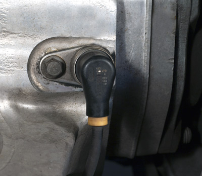
The installed view of a sensor. To extract it, you remove the bolt then withdraw the sensor. It's seldom that easy if dirt and corrosion works between the sensor body and the knuckle. Image: Author |
Click image for larger view
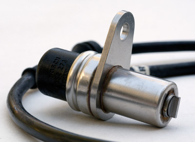
This is the business end of a rear wheel sensor and the part that sometimes seizes in the rear suspension knuckle. Image: Author. |
For replacement sensors, '86-'90 fronts and '86-'87 rears are no longer available from GM, however, NAPA, one of the better sources for C4 ABS hardware, sells replacements. The '91-'96 front sensor is part of the front hub and that assembly, along with rear sensors for '88-'96, are still available from GM parts sources such as Tom Henry Racing. On '92-up cars with traction control, occasionally, there can be a problem with the throttle cable system adjustment. Anytime you're troubleshooting a complaint of poor engine performance, check the adjustment of the all the throttle cables. Instructions are in the Service Manual.
|
|