2006 Corvette Z06 Adds Carbon Fiber Fenders
Corvette Z06 Adds Carbon Fiber Fenders
Molder meets GM's performance, weight-reduction goals and achieves 14,000-part production target with autoclave-cured prepreg.
by Jared Nelson, Contributing Writer
High-Performance Composites Magazine
Text and Images: ©2005 High-Performance Composites Magazine
November 2005, pg. 44-46
Correction to this article: The ply layup for the Corvette Z06 front fenders described on p. 46 features six layers, not eight. The layup sequence is 0°/90°/0°/0°/90°/0°, says Donald Lasell, the former Vermont Composites project engineer who was interviewed for the story.
Since its introduction in 1953, the General Motor's Chevrolet Corvette has been a trendsetter, with its fiberglass body, distinctive body styling and high-horsepower engines. It's also served as a test bed for new GM technologies, particularly in the areas of braking, engine development and new materials. In keeping with that tradition, the 2004 Z06 Corvette Coupe, the version equipped for highest performance, was selected as the test base to determine the feasibility of carbon fiber exterior body parts in a production scenario.

Corvette Z06 Carbon Fiber Fender Source: Karl Reque
Carbon fiber has had a difficult time breaking into the OEM automotive market. Hot among the tuner crowd, carbon parts sell well in the auto aftermarket, but few have the quality necessary to qualify as original equipment says Donald Lasell, project engineer for composite manufacturer Vermont Composites (Bennington, Vt.). Although DaimlerChrysler and Ford were working carbon into support structures -- the 2003 Dodge Viper's 3,000 pairs of front fender supports (HPC April 2003, p. 32) and the 2004 Ford GT's 4,500 rear decklid inner structures (HPC January 2004, p. 16), Corvette's 2004 LeMans Commemorative Edition Z06 marked the first attempt by a U.S. automaker to produce a carbon exterior body panel. Until that time, carbon parts with Class-A finishes had been the exclusive preserve of Italy's Lamborghini, Britain's McClaren and other hand-built sports cars produced in quantities of a few hundred.
When Tier 1 manufacturer MacLean Quality Composites (West Jordan, Utah) successfully molded, autoclave-cured and delivered 2,100 carbon/epoxy prepreg exterior hood panels for the Z06 LeMans (see HPC, March 2004, p. 33), the landmark achievement spurred GM engineers to pursue more carbon on a future model. A Z06 was not built for model-year 2005, but 7,000 were slated for 2006, offering an ideal platform for pushing the production envelope for autoclaved prepreg.
Equipped with a 505-hp 7.0-liter (427 cubic inch) engine, the 2006 Z06 delivers 23 percent greater power and has a higher top speed (198 mph/319 kmh) than the 2004 model (171 mph/275 kmh), says Dave Hill, Corvette's chief engineer. To maximize the car's power-to-weight ratio, Hill and fellow Corvette engineers sought ways to trim additional pounds from the car's body weight.
More carbon up front
To determine whether a part is feasible, GM considers five factors in its Part Selection Process: cost per kilogram of mass saved; location on the vehicle; tooling cost; ability to meet or exceed all base vehicle requirements; and paintability at GM's Bowling Green Assembly Plant without paint process modification. The location on the vehicle is critical to vehicle performance and forward locations are preferred. By reducing the weight at the front of the car, the center of gravity is moved further back, away from the engine mass. In addition, reducing the weight at the sides of the car decreases the energy needed to change vehicle direction, thereby reducing rolling moment (the tendency for the car to lean in the direction of the turn) through turns. The change in the center of gravity and reduced rolling moment enable the driver to comfortably maintain higher speeds through corners.
Since it was cost prohibitive to use carbon in both the hood and additional exterior body panels, the front fenders offered the best opportunity to further reduce vehicle mass and improve its performance. GM specified that carbon parts for the 2006 Z06 be made with T600-24K carbon from Toray Composites America Inc. (Tacoma, Wash.), the same fiber used in the Toray P3831C-190 carbon fiber/epoxy prepreg for the 2004 hood. Therefore, there was little doubt that the part could meet performance or paintability requirements. However, the fenders were much more complex parts than the hood, and part variation had to be held to within ±0.75 mm (±0.030 inch). Therefore, the key challenges Vermont faced were in the area of tooling and processing speed.
During the hood project, Lasell was the R&D product engineer at GM responsible for its design and validation. As the hood was moved forward into production, Lasell began development of a carbon fender, but shortly thereafter returned to his home state of Vermont and went back to work with former employer Vermont Composites. GM approached him there and asked Vermont to validate the fender production. Before bidding on the fender contract, however, Vermont had to prove not only to GM but to itself as well, that production of 7,000 sets of fenders was feasible.

Vermont Composites Source:
Typical Z06 front fender mold, showing removable inserts.
Retooling the tools
To do so, Vermont enlisted the help of Models & Tools Inc. (Troy, Mich.) for tool design. The fenders' complex shapes made tooling cost and the potential for die lock primary concerns. Since the Z06 would feature an 35-mm/1.38-inch increase in tire track width over the base model C06, the need for new tooling gave Vermont the opportunity to select more advantageous tooling material than the Invar used for the hood. To reduce the tool's thermal resistance and, as a result, reduce heat-ing and cooling times during the cure cycle, single-sided tools were made from P20 steel, which has a thermal conductivity three times greater than Invar -- 10.8 W/m-°C (225 BTU/in- hr-°F) compared to 32.5 W/m-°C (75 BTU/in-hr-°F), respectively. P20 steel is also much easier to machine than, thus reducing cost.
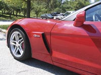
Close-up of carbon fiber fender in place on the 2006 Corvette Z06
Source: GM
The new P20 steel molds, however, have a CTE of 12.8x10⁻⁶ mm/mm-°C (7.1x10⁻⁶ in/in-°F) resulting in a greater shrinkage of the tool during the cool-down process. For the hood, heavier Invar tools had been used to take advantage of the almost negligible difference in the coefficient of thermal expansion (CTE) between the carbon and the mold of 5.4x10⁻⁶ mm/mm-°C (3x10⁻⁶ in/in-°F). To account for the different CTE between the part and the P20 steel tool and avoid die lock, each tool was designed with a main shell and five removable inserts, positioned accurately within the shell by means of tongue-and-groove locators and held in place by vacuum. After cure, the vacuum is released, and inserts can be removed from the shell and part individually to facilitate demolding. The tongue-groove locators permit the inserts to move slightly -- less than 1.6 mm/0.063 inch -- during the cool-down, to accommodate tool shrinkage.

A thermal profile model of the airflow inside of Vermont
Composite's autoclave as created by Quartus Engineering using IDEAS-ESC.
Source: Vermont Composites
Each insert is geometrically stable and weighs less than 11.3 kg/25 lb, making it easy for technicians to handle. In addition, each 318 kg/700 lb tool can be made from a single 9,525 kg/21,000 lb forged P20 billet. To minimize post-mold paint prep, the was engineered to strategically place the small, resin-rich flash lines, called "lifter lines," which occur at insert/shell seams, where they could be easily sanded manually during the finishing operation to achieve the necessary Class-A paint surface. To accommodate the almost three-fold increase in part production over the hood, Models & Tools constructed five sets of left-and-right fender tools.
Remodeling the cure cycle
MacLean's greatest challenge in producing the hood had been minimizing the autoclave cure cycle -- a challenge Vermont Composites revisited in the attempt to produce nearly seven times as many fenders. The company contracted with Quartus Engineering (San Diego, Calif.) to model the air flow characteristics in its 1.8m/6 ft by 6.1m/20 ft electrically heated autoclave. Quartus created a virtual 3-D model of Vermont's autoclave, in which four virtual fender tools could be placed and oriented in various ways to determine the ideal position for uniform heating, using I-DEAS finite element analysis software developed by MAYA Heat Transfer Technologies Ltd. (Montreal, Quebec. Canada), a supplier of advanced thermal and fluid flow analysis software. The ESC Flow add-on for the I-DEAS suite is designed to simulate 3-D airflow and thermal behavior, enabling engineers to resolve thermal engineering problems. Once the ideal tool position was established, it was determined analytically that the cure cycle time could be held under 90 minutes, which Vermont Composites validated in subsequent testing. Vermont is currently producing fenders using this positioning with four tools in each cure and maximum capacity of six tools.
Designing a load-worthy layup
Vermont Composites spent a significant amount of time developing what was intended to be a balanced six-ply layup, using unidirectional T600 24K tape impregnated with Toray's G83 quick-cure epoxy resin. But the six-ply schedule lacked sufficient stiffness, resulting in "oil canning," term used when a part tends to retain deflection that results after a load is applied and then removed, rather than springing back to its original shape. To eliminate this problem, two additional plies of prepreg were added to the layup schedule, both in 0° orientation (parallel to the car's length), to increase the part's nominal thickness from 0.8 mm to 1.2 mm (0.031 inch to 0.047 inch). The result was a balanced eight-ply lay-up (0°, 90°, 0°, 0°, 0°, 0°, 90°, 0°). Additional "spot" plies were placed in several select areas where greater stiffness was required.
Ultimately, GM expended $500,000 on the tooling design and modifications, to achieve a weight reduction of 12 kg/26.5 lb per car, meet all part performance and appearance specifications, and was able to manufacture the required 7,000 pairs within production time constraints, making the fender project a big win, notes GM design release engineer Mark Voss.
Looking forward
Vermont Composites has a commit-ment from Toray for enough material to produce the 14,000 fenders per year through 2006, and its contract with GM runs through 2010. However, both GM and Vermont Composites are looking at lower-cost fiber options for the 2007 model year and beyond, working with Toray and other prepreggers. In order for new materials to be used, however, the validation process would have to be repeated to make sure they attain the properties set forth in the GM specification for the material Toray currently supplies. In addition, a new prepreg would have to meet requirements for dimensional stability, surface finish and paint adhesion. Additional cost reductions, however, could help GM justify using the fender on the base Corvette C06, at 160 cars per day, Lasell notes, acknowledging that further improvement will be needed to abbreviate processing time and increase the production rate.