C6 Corvette Z06: The Heads On Test - How to Perform Low-Accuracy Measurement of LS7 Valve Stem to Guide Clearance - Page 1 of 4
by Hib Halverson
© December 2014
No use without permission, All Rights Reserved
Let it be known: a "wiggle test" - measuring a Chevrolet V8's valve stem-to-guide clearance with the heads on the engine--is not easy to accomplish. Done correctly, even for a professional service technician, it can be tedious, time consuming and even confusing at times.
No doubt, DIYs are reading this. If that's you, know that we made some assumptions: 1) you have the Factory Service Manual for your car to explain preliminaries to a wiggle test which are not detailed in this article, 2) you have experience with engine work such that you can disassemble then reassemble your engine's valve train and 3) you have access to and operational knowledge of the proper tools and measuring equipment. If you don't meet #2 and #3, let a Chevrolet dealer or independent service shop familiar with GM V8s do the work.
Explanations of wiggle testing are posted at various locations on the web and some are incorrect. An example of improper wiggle testing procedure is located in the C6 Z06 area on the Corvette Forum. The procedure discussed in the first post of that thread ignores an important principle of metrology--the science of measurement--which is discussed later in this article.
Even the Factory Service Manual method is problematic in that, of the two drawings which show measurement of stem-to-guide clearance, the first shows a procedure which ignores that metrological principle and results in inaccurate data and the second, along with the manual's instructional text, is impossible to duplicate on an LS7 head.
While on the subject of the Factory Service Manual, we should also note that, while it's not specifically stated, GM's intent is that valve-stem-to-guide measurement sessions be done with the cylinder heads removed from the engine. While that's how it is to be accomplished at the dealership level, provided the measuring process is done correctly, it's not necessary to remove the heads. If the wiggle test is performed properly, it can be done with the heads on or off the engine. We've done it both ways and given proper set-up of the measuring gear, the results are the same.
Finally, if the measuring equipment is not used properly, obviously, you risk inaccuracy. Such errors may have you decide valve guides are worn when they are not. The suggestions in this article will result accurate wiggle testing.
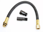
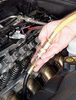
Besides the tools service technicians would have, you'll need a source of compressed air to apply air pressure to the cylinder which you are testing. This requires a special hose assembly that screws into a spark plug hole and accepts a standard air chuck on the other end. We used a Crane Cams "Cylinder Pressurization Kit" (PN 99474-1) for this.
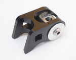
You'll, also, need a special tool for to compressing the valve springs of heads installed on engines. One of the compressors we used for this article was a Lingenfelter Performance Engineering "Valve Spring Compressor" (PN L950025297). The LPE compressor bolts to a rocker arm mount using a stock rocker bolt. It has a 3/8-in. square drive hole on each side and we used a 3/8-ths breaker bar to provide force to compress the spring. While the LPE compressor is cost-effective and simple to use, its one drawback is that the retainer moves in an arc as the spring is compressed.
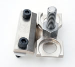
A spring compressor of a different design is made by LSM Racing Products and sold by Summit Racing. It compresses the intake and exhaust springs simultaneously with force being applied straight down rather than in an arc reducing possibility of the retainer contacting the valve stem. The LMS compressor is the screw type so it takes longer to use but it does two valves at once. Use caution when purchasing spring compressors like this. Some are claimed by their makers to fit LS7s but they do not. We tested Summit's LMS compressor and it, indeed, works on an LS7 and works quite well. The easiest way to obtain the LMS compressor is to buy it from Summit. The tool's Summit part number is LSM-SC-167.
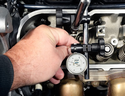
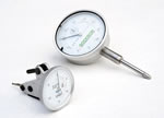
Wiggle testing requires a measuring device which is accurate to .0005-in. and can display on a dial or digitally. A traditional dial indicator can be used and likely will be the choice of many. For this article we used one (PN EDI-005) from Goodson Shop Supplies. It is affordably-priced, has one-inch travel, reads in increments of .0005-in. and can be used with a variety of standard indicator mounting devices. Another type of measuring tool good for wiggle testing is a "test indicator". In fact, they are a better choice because they can measure stem-to-guide clearance right at the top of the guide. The downside of test indicators is that they are more expensive. For this article, we used an "X-Test" Vertical Test Indicator (PN 52-562-005) available from Fowler High Precision. The X-Test reads to .0005-in. and the X-Test kit includes mounting adapters which attach to a standard indicator base. While we used both dial and test indicators in the several wiggle tests we did for this article, the Fowler X-test is our favorite.
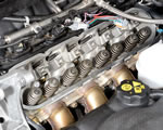
You wiggle test valve stems in pairs by cylinder, starting with number one. The stem-to-guide clearance measurement is done with the valve spring, retainers, locks and valve stem seals removed. Prepare for wiggle testing GM Gen 3/4/5 V8s by removing the spark plugs, the coil assemblies with plug wires, various PCV system pipes, rocker covers and all 16 rocker arms.
Install the Cylinder Pressurization Kit, but don't connect to air pressure just yet. Turn the crankshaft clockwise until #1 piston is moving up to top-dead-center (TDC). It's easiest to do this using the alternator pulley nut which you can turn with a socket. Listen for air escaping from the hose assembly you just installed. When you hear that, the piston is nearing TDC. Get the piston to exactly TDC by feel. Remove the hose, then use a long, wooden or plastic stick or similar tool to touch the piston top through the spark plug hole. Turn the engine slowly until the dowel stops moving out then starts moving in. Still feeling with the dowel, reverse and go back half the distance of your last movement. Do that a second time and the piston will likely be right at TDC. The reason you want the piston at TDC rather than bottom-dead-center (BDC) is once you have the valve springs removed to do the wiggle test, the piston at TDC prevents the valves from falling into the cylinder.
Now reinstall the air hose and pressurize the cylinder with shop air. If the piston is not at TDC, air pressure will push the piston down and you'll have to disconnect the hose and get the piston to TDC, again. Note that small air compressors may have trouble maintaining enough pressure to keep the valves closed. If that's your compressor, go rent a more powerful unit. Once the piston is at TDC and the cylinder is pressurized, remove the alternator because it's easier to wiggle test #1's valves with it out of the way.
