Stop to Match the Go - All About 1986 - 1996 C4 Corvette Antilock Brake and Traction Control Systems - Page 1 of 3
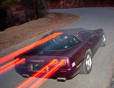
Image: Author
© 2009 by Hib Halverson
No use without permission, All Rights Reserved
![]() Discuss this article
Discuss this article
As I write this, the NASCAR Sprint Cup Series' annual pilgrimage to New York's famed road course, Watkins Glen International, is on TV. Road racing a Cup car-3400 lbs, 850-hp, small tires and no ground effects-has got to be the most fun you can have except for maybe sex and stuff that's illegal.
Jeff Gordon (#24 DuPont Chevrolet) and Tony Stewart, (#20 Home Depot Chevrolet) are running 2nd and 4th. Each has three wins at the Glen and Gordon has three more at NASCAR's other road race venue, Sonoma, California. Obviously, they're very talented drivers, but what connection do they have with the subject at-hand?
Great car control under braking.
Be it a Cup car or your Corvette, the tires which provide traction and they do that best when there's some slip between them and the road. Under braking, this is when the tire rolls slower than the car is moving but is not locked-up. Engineers call this "negative slip."
Braking to near wheel lock-up (aka "threshold braking") is a requirement if you want to be a road racer. The problem is: to be consistently good at threshold braking requires significant driving skill, experience and very good feel for the car. At the level Gordon and Stewart race, such qualities are instinctive. For the rest of us; there are antilock brakes.
Some History
Between 1986 and 1992, two automotive breakthroughs were four-wheel antilock braking systems (ABS) and traction control systems (TCS) as standard equipment on high-volume cars. The C4 Corvette was at the front of both trends. ABS was perfected by the aircraft industry. An airliner sliding off a slick runway into the weeds is, at best, disconcerting. It's bad PR for the airline and damages a multi-million-dollar piece of equipment-not to mention the possibility of injuring passengers. Half a century ago, as all-weather air travel became more common, pilots, engineers, along with, no doubt, airline risk management folks, desired brakes which could be applied, full-force, but, on slick runways, would automatically modulate to resist wheel lock-up and loss of control. In the 1950s, the British firm, Dunlop, developed "Maxaret", the first, practical, antilock brakes for airplanes. Today, just about anything in the air the size of a Cessna Citation or larger has antilock brakes. In the early-'60s, Maxaret, an electro-mechanical system, was adapted to the Fergeson P99, an obscure, British Formula 1 race car and, later, the Jensen FF, a just-a-bit-less-obscure, late-'60s, British road car.
In the U.S., Kelsey-Hayes developed an analog-computer-controlled, rear wheel ABS, known as "Sure-Track" which was optional on 1969 Lincoln Continental Mark IIIs and 1970 Oldsmobile Toronados. In the mid-'70s, K-H experimented with a Sure-Track off-shoot which was doubled-up to make a crude four-wheel ABS. Chevrolet had enough interest in this research to have K-H fit the system to a C3. After evaluation, this system was deemed not ready for prime time. Meanwhile in Germany, Robert Bosch Corporation developed a digitally-controlled system. Its second generation, "ABS-2", the first digital system on a production car, was an option on 1978 Mercedes-Benz S-Class and BMW 7-Series sedans.
By the early '80s, a more developed ABS-2 was available and, around the same time, Bosch and Chevrolet were negotiating the use of Bosch fuel injection parts on Corvette and Camaro for model year 1985 (MY85). During those meetings, Bosch pitched ABS-2 to the Bow-Tie guys.
Paul King, Chevy's Engineering Director at the time, eventually decided all '86 Corvettes would have ABS, making them the first cars in North America to have four-wheel, antilock brakes and one of only two brands in the world at the time to have them as standard equipment.
It really was an elegant idea: a digital computer doing "threshold braking" in a faster-acting and more consistent manner than can 99.5% of most Corvette drivers. And, in the front, when necessary to preserve steering control, doing it on a "per-wheel" basis, a feat no driver-even those named Gordon or Stewart-can accomplish. It was a risky decision for Chevrolet because of the expense. According to retired, Corvette Chief Engineer Dave McLellan's excellent book, Corvette from the Inside, a full 10% of the cost of an '86 was in its antilock brakes. ABS-2 was used until MY89. From MY90 and '91, an improved variation, " ABS-2S" was used. From '92-'94 on the base car and from '92 to '95 on ZR-1, there was yet another version, known as "ABS-2U".
The Components
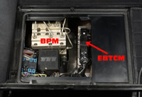
C4 antilock has two main hardware devices: the "electronic brake control module" (EBCM) and the brake pressure modulator (BPM), both in the compartment behind the driver seat. For ABS-2 and -2S, the EBCM and the BPM are separate but, for ABS-5, they're a single unit.
The EBCM (some say "ECU", "ABS controller" or "brake controller") is the brain of the system. It's a computer which controls the BPM based on its programming and information about vehicle dynamics parameters. There are five controllers: MY86-'89, '90-'91, '92-'94/'95 ZR-1, '95-base and '96. From '92-up, it's correctly known as an "electronic brake and traction control module" (EBTCM) because of the addition of traction control capability.
The BPM (sometimes called a "modulator valve" or a "hydraulic unit") is both the heart and the muscle of the system. Its key parts are solenoid-operated valves which control brake pressure at the left front, right front and both rear wheels; a high-pressure pump, which returns brake fluid to the master cylinder when necessary; an accumulator; some dampers, microfilters and various ball check valves. There were three BPMs: '86-'91, '92-'94 base/'95 ZR-1 and '95/base-'96. The major difference between the first unit and the second two is the latter's ability to control the rear brakes independently when operating in TCS mode.
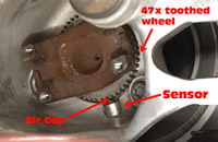
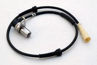
The ABS needs wheel speed data and, because its operation must be near instantaneous, that data must be high-resolution so only a short period of wheel speed data acquisition is required for the EBCM to determine if ABS intervention is necessary. Each wheel hub has a 47-tooth ring and a magnetic-inductive sensor in each suspension knuckle. There is a tiny gap between the teeth and the sensor's coil. The rings rotate at wheel speed and each time a tooth passes through the sensor's magnetic field, it generates a pulse. The frequency of this AC voltage is proportional to wheel speed. Since it's a high-resolution "47x" signal, changes in wheel speed can be detected very quickly and precisely.
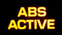
The '86-'89 ABS has a lateral acceleration switch which signals the EBCM when the car is generating more than 0.5g "lat". The '90-'96 systems use a sensor which actually measures lat rather than just turning on at .5g. When the module receives the switch's signal or data indicating high lat, it alters antilock strategy to better suit operation during high-g turns. The system advises the driver when it's active with an "Antilock On" or "ABS Active" light. If it experiences a problem, an "Antilock" or "Service ABS" light (some call it the "service light") comes on.
How does all this Work?
ABS is transparent to what engineers call the "base brake" system until it's needed. It's, also, "fail safe" so, if there's a problem, it shuts off, leaving the base brakes unaffected. It's a three-channel system, meaning it outputs three control signals: one for the left front brake, one for the right front and a third for the two rears. At the rear, it's a "select-low" system meaning the wheel with the least traction determines the level of brake control.
When you turn the key on, ABS tests its electronics and, once you drive at least 3.6 mph in either direction, it tests its hydraulic functions. This verifies proper ECBM function and operates the BPM's solenoids and pump momentarily. The driver usually hears the pump run and may feel its momentary operation if his/her foot is on the brake. ABS goes active when one or more wheel sensors indicate a rate of change in wheel speed characteristic of impending wheel lock-up, that is: the wheel(s) are slowing so quickly that lock-up is inevitable. If this is happening at the left front. The ECBM applies a 2.5 amp current to the BPM solenoid valve controlling brake pressure to the left front caliper. The valve moves to the "pressure hold" position, blocking flow and keeping fluid pressure from going higher, regardless of how much harder the driver pushes on the brake pedal.
The ECBM continues to watch wheel speed. If the trend towards lockup doesn't abate, the controller doubles the current flowing to the solenoid. With five amps across it, the valve moves to the "pressure decrease position" and, even if the driver is pushing harder, brake pressure drops and lock-up is no longer eminent. At this point, the pressure decrease stops the wheel's impending lock-up. Once the ECBM detects that, the solenoid is released and brake pressure builds, again, however, if the wheel starts to lock a second time, the controller will, again, command either the pressure hold or decrease modes. This cycle continues until lock-up abates and it can happen up to 10 times per second.
When solenoids operate in the pressure decrease mode, if brake fluid released from the base brake system is not replenished, the pedal will bottom. The ABS pump solves that problem by pumping fluid back into the base brake system. In the very short time the pump is coming up to speed, fluid is temporarily stored in an accumulator. This pump makes a buzzing/grinding noise and causes a vibration the driver feels through the brake pedal which serves as tactile feedback that ABS is active.

