Engine Oil Deep Dive - CAC's Comprehensive Look at Engine Oil and Flat-Tappet Camshaft Durability - Page 1 of 6


Image: Author
© 2009 by Hib Halverson
No use without permission, All Rights Reserved
![]() Discuss this article
Discuss this article
For several years, Corvetters have read and heard rumors, discussions, arguments, fairy tales and even a few facts about accelerated wear of flat tappet camshafts and lifters in overhead valve engines. Allegedly, engine oil has a key role in this problem. With this article, the Corvette Action Center examines the problem, its severity and how can it be solved.
Valvetrain Basics
From 1953 until 1986, production Corvette engines had flat tappet cams. Since then, with one exception, they have used roller tappets. The exception was the LT5 in 1990-95 ZR-1's, but, because it had overhead cams and direct-acting, bucket-type, flat tappets; it's only peripherally related to this wear issue.
While flat tappets haven't been in stock, overhead valve (OHV) Vette engines for over 20 years, they are still available from aftermarket, high performance camshaft vendors mainly because of their lower cost. They are, also, available as original equipment (OE) replacements. Lastly, there are a few hundred thousand or so "survivors" '53-'86s with original valvetrains. Executive summary: many flat tappet engines are still on the road, today.
In an OHV engine, during valve opening, the camshaft lobe pushes the tappet some call it a "lifter" or a "follower" against valve spring pressure multiplied by the rocker arm ratio. After Oldsmobile pioneered high-rpm OHV engines in the early-1950s, higher valve spring pressure to the extend engine speed range, inspite of the OHV design's high valvetrain mass, became common.
 |
 |
Click image for larger view
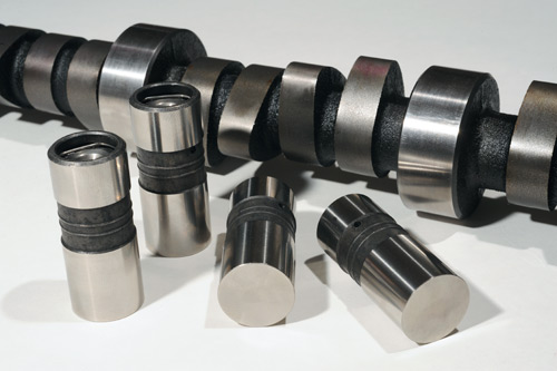
This was typical of cams and lifters in Corvette engines for a generation. The bottom face of the lifter is why people call them "flat" tappets. In reality, the name is incorrect, as you'll read later. Image: Author |
Click image for larger view
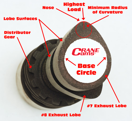
Courtesy of the people at Crane Cams, we obtained this short, saw-cut section of a Small-Block Chevy flat-tappet cam. Using a little Photoshop knowledge (we have enough of that to be dangerous) we've shown you some key aspects of camshaft geometry. Image: Author |
The combination of spring pressure, rocker ratio and inertia makes for high load concentrated on a small, elliptically-shaped area where the lobe and tappet make contact. The area of highest load surrounds a point where what valvetrain engineers call the "minimum radius of curvature" or "nose radius" intersects the lobe surface. Imagine the nose of the cam lobe as a series of segments of circumferences of circles of varying radii, the shortest of which is a line from the lobe surface to the center of the circle closest to that surface. This point is at or, in the case of asymmetrical lobe profiles, near maximum lift. Since the lobe slides or scrapes across the tappet face and both are under high load; that contact area has the potential for high rates of wear.

Imagine one of these babies with its weight (about 250,000 lbs) concentrated on an area one-inch square and you'll better understand the load at the lobe/lifter interface in an engine fitted with a flat-tappet same.
Image: Boeing Commercial Airplane Company
In a stock Corvette, flat tappet engine, pressure near max. lift can be up to about 180,000 psi, a number that our research indicates was GM's "general rule" for maximum lobe/lifter interface pressure in production flat tappet engines. That number goes back many years, perhaps as far as the mid-1950s. It is still valid today for the part of engine oil certification tests which validates durability of flat tappet valvetrains.
In engines having aftermarket, high performance cams, higher tension valve springs and/or higher ratio rocker arms the pressure will be more, upwards of 200,000-psi. All-out racing, flat tappet valve trains are around 250,000-psi., or 125 tons per square inch, and a few, such as in NASCAR Sprint Cup engines, can be closer to 300,000-psi. How much is that? Imagine a Boeing 757 jetliner sitting on a postage stamp.
As incredible a load that might seem, both Crane Cams', Chase Knight, and Comp's, Billy Godbold, told us that the dynamic loads are even higher because valvetrain motion is violent and complex.
"If you just rotate by hand, the cam/tappet interface will see the highest load at the nose," Godbold told us. "However, as rpm increases, average load goes down, but you get surge (load fluctuations) with the spring coils running into each other. Even at moderate rpm, you'll get coil-to-coil interaction. Any dynamics model which doesn't include that will be in error.
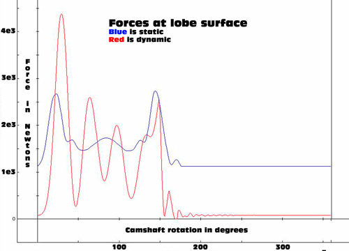
Data, developed by Comp Cams, shows the difference between the static pressure on the cam lobe and dynamic pressure.
Image: Comp Cams
"This interaction is not coil bind. The spring wire vibrates and touches other coils. It starts a wave though the system like thumping a slinky. Depending on the spring's frequency, this wave may go to the last coil then reflect back hitting the retainer with force opposite the direction the retainer is moving. Retainer movement combined with force applied in the opposite direction creates very high loads.
"At low rpm, the spring might surge five times. At high rpm, it might surge once, then do what I call 'McDonalding' the valvetrain lofts (the tappet is thrown off the lobe) then smacks the nose and bounces a second time. It looks like two arches. The loads are tremendous - four or five times the open pressure.
"Trying to see this as a static system doesn't work with aftermarket performance cams." Godbold continues. "The only ways you get the dynamic load is to computer model valve train motion or measure it. Those loads are so much higher than static loads, it's not even funny."
Managing Wear
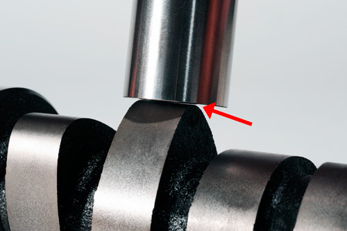
Three strategies mitigate wear of cam lobes and lifter faces. The first is mechanical engineering. We lied. Flat tappets, well...they're not flat. Their faces are slightly convex or "crowned". In addition, the lobe's longitudinal profile has a very slight taper, usually .0012 to .0020-in., and, finally, the lifter axis is offset from the plane bisecting the lobe face. In combination, these features cause the lifter to rotate as the cam lobe rubs across its face. That eliminates the lobe contact point dwelling in the same place on the lifter face, causing high levels of wear.
 |
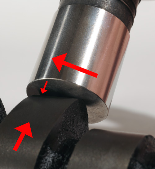 |
Click image for larger view
With the lifter having a slight convex face and the lobe having a slight taper, the lobe/lifter interface is actually not in the center of the lobe. Image: Author |
Click image for larger view
The geometry of the lobe/lifter interface is such that the liter rotates in its bore in the block. Image: Author |