Ruthless Pursuit of Power: The Mystique of the C6 Corvette LS7 Engine - Page 11 of 26
Ruthless Pursuit of Power: Lucky Seven Edition: The Mystique of the 7-Liter, 7000-RPM, LS7 - Page 11 of 26
 |
 |
by Hib Halverson
© May 2013— Updated: November 2014
No use without permission, All Rights Reserved
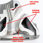
"The exhaust side is very similar," Gerdeman continued. "Again, there's a unique area schedule. We spent a lot of time on the exhaust fine tuning that. Also, the exhaust has even more of a pronounced difference between the short turn and the long turn sides.
"Area past the guide is critical, but we still had to keep as-cast material around the valve guide for temperature control to avoid durability issues. In some (racing) cylinder heads, almost all the as-cast aluminum is gone--racers will feather the aluminum material out almost to a knife-edge adjacent to the guide. We've got to still meet our durability targets, so we can't machine it all away. The valve guides are installed in the head prior to the CNC machining. We have an as-cast port shape which provides roughly 1.5-millimeters of finish stock (left for the CNC work) everywhere. When they do the CNC machining, they have to come up and clear that valve guide insert. The CNC program can only get so close, so you're going to see as-cast material (at the end of the guides) just because of that.
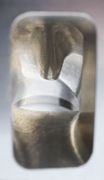
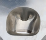
"It's really designing the entire chamber as a complete system. It's the maximum unshrouding on the sides where the valves come closest to the bore wall. The key is developing blends and transitions so the airflow across the valve seat stays attached to the shape of the chamber and ports as much as possible. In the case of the inlet, air flow comes across a very open area towards the exhaust side and you want it to stay attached to that wall. Any time you start getting detachment of the air flow, whether it's the ports or the chamber, you get turbulence which drives your effective area down and you start losing air flow. It's like you're making the port or the chamber smaller.
"The four angles on the intake seat really help, even with high lift flow. The more angles you can cut, the more of a perfect radius you end up with. At low lift, a lot of flow on the inlet side is going to come from the unshrouding of the valve and how far it is from the bore. Then, at the higher lifts, it's how well you can keep that air flow attached to the walls and reduce turbulence.
"We worked the backside of the intake valve and the geometry transitions across the seat angles to valve stem. We, also, tried various valve margin heights and settled on what we have there as best for air flow."
Near the end of the LS7 cylinder head development, Gerdeman and his team looked beyond just air flow. Some of this research was done at Chapman Racing with a "wet flow bench" which mixes colored liquid with air flow inside a transparent bore to simulate a mix of fuel and air flowing into the cylinder.
They studied how the air and fuel mixed in the chamber as it flowed across the valve seat and as it continued to mix once the intake valve closed and the compression stroke began. The see-through bore and the color allowed the cylinder head engineers to observe the homogeneity of the air-fuel mix as it came past the intake valve seat and flowed across the chamber then into the bore as the piston moved down in the cylinder. The LS7's cylinder volume was huge and getting a homogenous a mix as possible was a challenge but an absolute necessity if the engine was going to meet fuel economy and exhaust emissions targets. They, also, looked at the homogeneity of the mix near the spark plug and, once the ignition kernel developed, how the flame front propagated across the combustion chamber.
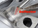
The engineers' observations at Chapman racing encouraged them to experiment with a aerodynamic device in the roof of the intake port between the valve guide and the long turn radius. Described by Dennis Gerdeman as a "wing," it looks more like a ridge or a deflector. It is intended to impart a specific directional swirl to the flow as it enters the cylinder bore while the piston moves down on the intake stroke.
The motion imparted by this deflector is complex. It's somewhat like swirl, towards the spark plug, but it, also, generates downward spiraling motion towards the centerline of the bore. In the end, this one feature of the LS7 intake port did much to enhance the homogeneity of the air-fuel mix in the engine's large cylinder volume and contributed to the engine's high combustion efficiency.
Interestingly, while Chapman's wet flow bench was cutting edge stuff in 2004, it's an anachronism, today. By the late '00s, GM's analysis capabilities had grown tenfold such that CFD, with an enhancement called "rain drop analysis," could simulate wet flow down ports, though valves and seats and into cylinders and do it in a few hours of computer time rather than weeks of work with flow boxes on a wet flow bench.
 |
 |


