Ruthless Pursuit of Power: The Mystique of the C6 Corvette LS7 Engine - Page 20 of 26
Ruthless Pursuit of Power: Lucky Seven Edition: The Mystique of the 7-Liter, 7000-RPM, LS7 - Page 20 of 26
 |
 |
by Hib Halverson
© May 2013— Updated: February 2016
No use without permission, All Rights Reserved
LS7 Valvetrain Geometry–Yay or Nay?
Another belief expressed by some is that two characteristics of the LS7's valve train geometry–the smaller, 12° valve angle and the 1.8:1 rocker arm ratio–cause excessive side loading of the guides and premature wear. We feel that the combination of: 1) the LS7's valve train geometry having been optimized such that, with the stock camshaft profile, the level of side loading is no more than that present in other Gen 3 and 4 V8 valve trains and: 2) that a change in valve angle–actually, a change in the angle of all the valve gear on the head–is not going to change side loading on the valve side of the rocker, discredits that belief.
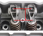
While the design of the LS7 valve train is sound from a geometric standpoint, once again, manufacturing quality is up for question. Research done by the Z06 owner's community indicates a problem, though less widespread than non-concentricity, with inconsistency in the distance between the centerline of the rocker arm pivot and the centerline of the valve guide.
We discovered content on the Corvette Forum, posted by forum member, John Hughes. An engineering analyst at Lockheed-Martin and a lifelong automotive DIY who does side work as a machinist, Hughes owns a Z06 with an LS7 which suffered worn guides. When he measured his engine's valve-stem-to-guide clearance at 78,000 miles, all of the exhausts and two of the intakes had worn beyond the .0037-in limit with some exhaust guides having clearances four times that limit. Additionally, all the rocker arm pallets–the part of the rocker which sweeps across the valve stem–had brown, crescent-shaped wear patterns and there were exhaust valve stem tips with worn edges. Those characteristics indicate that the rocker pallets had been sweeping off the edge of the valve stem tips. The result of the rocker sweeping off the edge of the stem tip is increased side loading of the valve and a higher rate of guide wear.
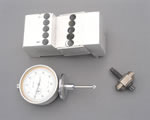
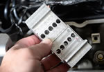
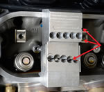
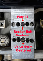
After his heads were repaired, a rocker arm geometry test, where one uses machinist's blue to analyze rocker arm pallet's movement across the tip of the valve stem, led Hughes to suspect the distance between the guide centerline and the rocker pivot was excessive. Hughes fabricated a gauge block to check that dimension. At the time the first revision to this article was posted in 2014, Hughes claimed to have personally checked 50 LS7 heads and found half of them with one dimension and a proper rocker "sweep pattern" and half with a dimension about .050-in. greater and exhaust rockers sweeping off the edges of the valve stem tips. The "Hughes Gauge Block" also checks rocker pedestal and valve stem heights, but so far, neither of those dimensions have been problematic. According to Hughes, the trouble spot is the distance between the rocker pivot and the guide.
Needing more data, Hughes began a "grass-roots research project" to measure more heads by loaning his Gauge Block tool set out to LS7 owners around the country who work on their engines. So far, another 52 heads have been measured with the same results–two distinct groups of measurements, one .050-in. larger than the other. Hughes told the CAC in an email that of the 51 sets of heads checked, 50 of them had both heads' rocker fulcrum-to-guide measurements in either one group or the other. Only one of the engines had one head with measurements in each group.
We were unable to obtain the factory dimension, but that 100 heads were checked and about half the rocker-pivot-to-guide-centerline distances measured one number and half measured .050-in greater indicates another potential problem with Linamar's machine work. Hughes told the CAC in a subsequent email, "As I previously mentioned, there were two distinct groups (of measured distances). It’s as if two (CNC) machines were being used for final head machining and one of them had a bad set up. If it was simply a tolerance problem, there would not be a gap between the two groups of measurements in which no heads' (rocker-pivot-to-guide-centerline) measurements were found."
Hughes went on to say that he believes that when the head has a pivot-to-guide distance that is too large, the cause is likely the valve guide bore having been machined in the wrong position rather than the valve guide, itself, having its inside diameter off center.
The real bad news about this inconsistent distance between the rocker pivot and the guide centerline is: currently, there is no fix for it other than replacing the heads and, at this point in time, the "Hughes Gauge Block" is not recognized as a way to detect, for warranty purposes, a problem with rocker-pivot-to-guide-center distance. As a result, anyone with low mileage heads having guide wear below the service limit, but improper rocker-pivot-to-guide-centerline distance will be in a tough spot because he/she will have to wait until the guides are worn before making a warranty claim.
The good news–ok, maybe it's not all that great–is that the amount of LS7 heads with improper rocker pivot to guide distance seems to be less than the number of LS7 heads with non-concentric guides and seats.
Of special interest to those with LS7s which are out of warranty is that, while heads with this problem and which use stock rockers cannot be repaired, there is an aftermarket fix and that is to convert to a roller tip rocker arm typical of what Crane Cams, Yella Terra and offer. While a set of aftermarket rockers may solve the problem with the rocker sweeping off the side of the valve stem tip, some aluminum roller rockers have more mass on the valve side of the rocker than do factory rockers, so a valve spring change may, also, be required if the engine's valve train dynamics are to remain stable above 6600 rpm.
 |
 |


