Ruthless Pursuit of Power: The Mystique of the C6 Corvette LS7 Engine - Page 4 of 26
Ruthless Pursuit of Power: Lucky Seven Edition: The Mystique of the 7-Liter, 7000-RPM, LS7 - Page 4 of 26
 |
 |
by Hib Halverson
© May 2013— Updated: November 2014
No use without permission, All Rights Reserved
"Significant change was needed to increase engine throughput." John Rydzewski stated about the engine's displacement. "Increasing bore and stroke were enablers for the increased performance. Some of the executive leadership desired a displacement such as the iconic, 427 cubic inches. Our analytical and geometric studies supported the 104.775-mm (4.125-in) bore and 101.6-mm (4.0-in) stroke (7.008-liters or 427.484 cubic inches). They were selected for the LS7 program."
Ya think some of John's "executive leadership" had been waxing nostalgic about 427 Vettes? Having dreams of four-inch-plus pistons and two-inch-plus intake valves? Hearing the seductive sound of a high RPM valvetrain motion? Feeling the thump of a big-inch motor pulling hard in the low-mid-range? Listening to the lopey idle of a big cam? Yeah--that's what those car-guy, true-believers were doing. Thank the car gods there were a few of them left.
And what of the six-four? Well--it was never considered for production--never made it into a car, in fact, but its development was not for naught. Five years later, the 6.4's head appeared on the LS3 and, in 2009, after a slight revision in intake port design along with a change in material and foundry process, it, also, became the LS9 cylinder head.
Five hundred horsepower from a normally-aspirated V8 while meeting emissions and fuel economy standards was a tall order in late Spring 2003, when full-scale LS7 development began. Muscaro's Small Block Team was soon burning the midnight oil in a ruthless pursuit of power with a 500-horse, 7000-RPM, emissions-legal, no-guzzler, 427 as its objective.
Actually, perhaps as many kilowatt hours were burned as "midnight oil". General Motors has significant computer modeling and simulation resources. Computer software tools such as "Finite Element Analysis" (FEA), "Uni-Graphics" and "Computational Fluid Dynamics (CFD) were used during design and development. A different block casting and a new head were in the program even before the computers got warmed-up. Other key features of the engine were determined by computer modeling--a forged steel crankshaft, pressed in, rather than cast-in-place, liners and titanium connecting rods were, also, deemed necessary through modeling.
The LS7 was developed on Sam Winegarden's watch as Small-Block Chief Engineer, He tells a great story about computer modeling. "I was still Small-Block Chief, the first time these guys could model combustion. This would have been back in about '03 or '04. Dr. Gary Mendruziac (formerly with GM Advanced Research) started us down this journey and I always remember this. It took him one week to do the model for the induction stroke. Second week, he did the compression stroke. Third week he burned it (power stroke). The fourth week was the exhaust stroke--a month of computer time to model one cycle. Now, I can do that in a matter of a few hours. Just to give you an idea for how much faster the computers have gotten in that length of time. Eight years and we've gone two orders of magnitude faster."
GM spent a couple of months on LS7 computer work before the first LS7s were assembled by Katech in the Summer of 2003. Shortly after that, more early development engines were done by Powertrain's experimental engine assemblers in Pontiac. Starting on 24 February 2004, development engines were built at the Performance Build Center.
Special Block and Crank
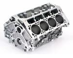
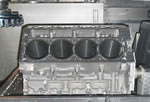
GM's production, aluminum V8 bare blocks, or "cylinder cases" are cast by Nemak, a world-class foundry in Monterrey, Mexico, which supplies engine manufacturers world-wide. The LS7 case shares qualities Gen 3/4 engines have had since their 1997 debut: deep-skirted, 319-T5 aluminum block, long head bolts threading deep into its main bearing webs, six-bolt main bearing caps, a center thrust bearing and gray iron liners which are centrifugally-cast for increased density to enhance strength and allow thinner cylinder walls. All this makes a lightweight, rigid, block structure offering good durability and reduced friction--all important basics for a specialized engine like the LS7.
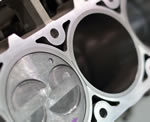
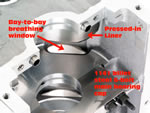
While the case is a Gen 4, it's a little different from its 6.0 or 6.2-liter siblings used in other C6es. It has pressed-in, rather than cast-in-place liners and its water jackets had to be altered to accommodate them. The LS7's bore, 104.775-mm, 3.18-mm larger than that of the existing LS2, was greater than cast-in place liners would tolerate and still have adequate cylinder wall thickness, but it works if partially-siamesed, pressed-in liners are used. The liners, also, extend farther into the crankcase than do the cast in-place units. Because of the the LS7's, long stroke, the extra length is necessary as a guide and support for the thrust side of the piston skirt.
John Rydzewski told us that, after casting, LS7 blocks are shipped to a Linamar Corporation facility in Guelph, Ontario, Canada for rough machining, installation of the pressed-in liners, and finish machining operations. One of those operations, machining "hone over-travel clearance", became a major issue during the engine's late development stage. "When the block is honed, the bottom of the honing tool needs clearance so it doesn't contact the block below the bore," John Rydzewski stated. "Before the honing operation, the block is machined in that area to provide clearance. The resulting surface geometry has a big impact on the block structure. Hone over-travel clearance used to be machined (LS1, -2, -6 and early LS7 development cases) with a 3-mm radius. To get more strength in that area, we eventually changed to a more gentle, 8-mm radius. That was a big durability enabler at the LS7's power level."
As the pistons move, they force air in and out of the spaces (or “bays”) beneath them. At high RPM, these flow reversals are rapid, violent and really whip up the oil as well as creating power loss. One way to mitigate this problem is to vent each bay to its neighboring bays. Like other Gen 3 and 4 blocks, production LS7 blocks have openings or "windows" their main bearing webs between bays for this “bay-to-bay breathing". Rydzewski went on to say, "Hone over travel machining, affects the size of the resulting windows in those bulkheads which are very significant to bay-to-bay breathing and horsepower."
 |
 |


